Hand Sign Recognition via Deep Learning on Tightly Coupled Processor Arrays
Involved Projects:
Contributing Researchers/PIs:
C. Heidorn, D. Walter, J. Teich
Movie: Hand Sign Recognition via Deep Learning on Tightly Coupled Processor Arrays
Predictability of Timing through Invasive Computing
Involved Projects:
Contributing Researchers/PIs:
S. Roloff, S. Wildermann, F. Hannig, J. Teich
Abstract
The following demonstration presents the capability of invasive computing to drastically increase the predictability of timing of the execution of complex stream processing applications such as a computer vision algorithm chain - object detection - on Multi-Processor Systems-on-Chip (MPSoC).
Object detection algorithms are used in robotics and other application domains to detect certain objects in a video stream to control, for example, the movement of a robot.
A brief overview of the individual tasks in an object detection algorithm chain is depicted in
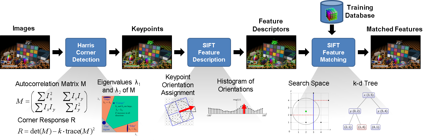
Figure 1: Object detection task chain.
In the following scenarios, this task chain is executed on an invasive MPSoC.
Depending on the claimed resources and interference with other applications, different latency and throughput values as well as different variations of these values (jitter) are determined.
It will be shown that using the concepts of invasive computing, these variations as measure of predictability may be reduced by isolating applications through exclusive reservation of resources.
The evaluation of the following scenarios was done using the InvadeSIM simulator.
The architecture configuration is shown in
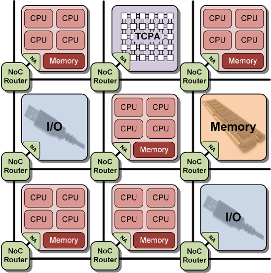
Figure 2: Target architecture.
Scenario I
The first scenario considers a non-invasive execution of a FIR filter and a motion planning application besides the object detection application.
In this case, it might happen that the other applications are mapped on the same tiles as where tasks of the object detection applications are running.
The considered application mapping on the architecture tiles is depicted in
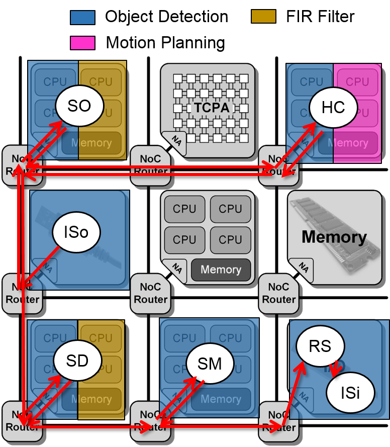
Figure 1: Mapping scenario I.
Video 1: Processor utilization scenario I (12 input images).
The simulation of this scenario results in an average latency of 180 ms (to process one image) and an average throughput of 17.9 fps. Furthermore, the variability of the execution in terms of jitter in throughput and latency as measure for predictability are maximum 30% and 29%, respectively. Due to non-exclusive execution, the required throughput cannot be met in this dynamic scenario. The object detection application is disturbed by the overlapped execution with the other applications and the user requirements on throughput of 25 fps cannot be guaranteed. The next scenarios will show, how Invasive Computing helps to satisfy user requirements, where non-invasive executions cannot guarantee such requirements and to provide predictable timings by exclusive reservation of resources.
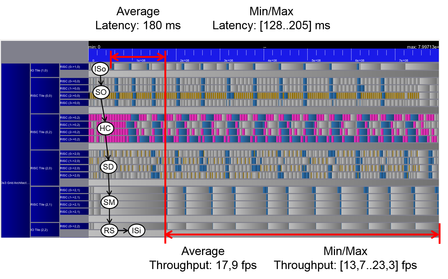
Figure 2: Trace scenario I.
Scenario II
In this scenario, the same applications are considered, however, they are mapped on the architecture using Invasive Computing concepts.
Each application first invades its required resources and then they are executed on them exclusively.
The result of the application mapping is shown in
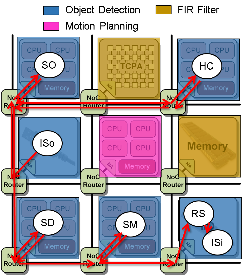
Figure 3: Mapping scenario II.
Video 2: Processor utilization scenario II (12 input images).
The simulation of this scenario results in an average latency of 92 ms and an average throughput of 25 fps, even that there are two other applications running on the platform. Furthermore, the jitter in throughput and latency are reduced compared to the non-invasive execution. They are maximum 18% and 7%, respectively. This results show that Invasive Computing is able to a) satisfy given user requirements, if an invasion is successful, where non-invasive executions cannot guarantee such requirements and b) provide predictable timings by exclusive reservation of resources. The following scenarios show a characterization of the object detection task chain, when no other applications are interfering in order to determine throughput and latency values according to different task to resource mappings.
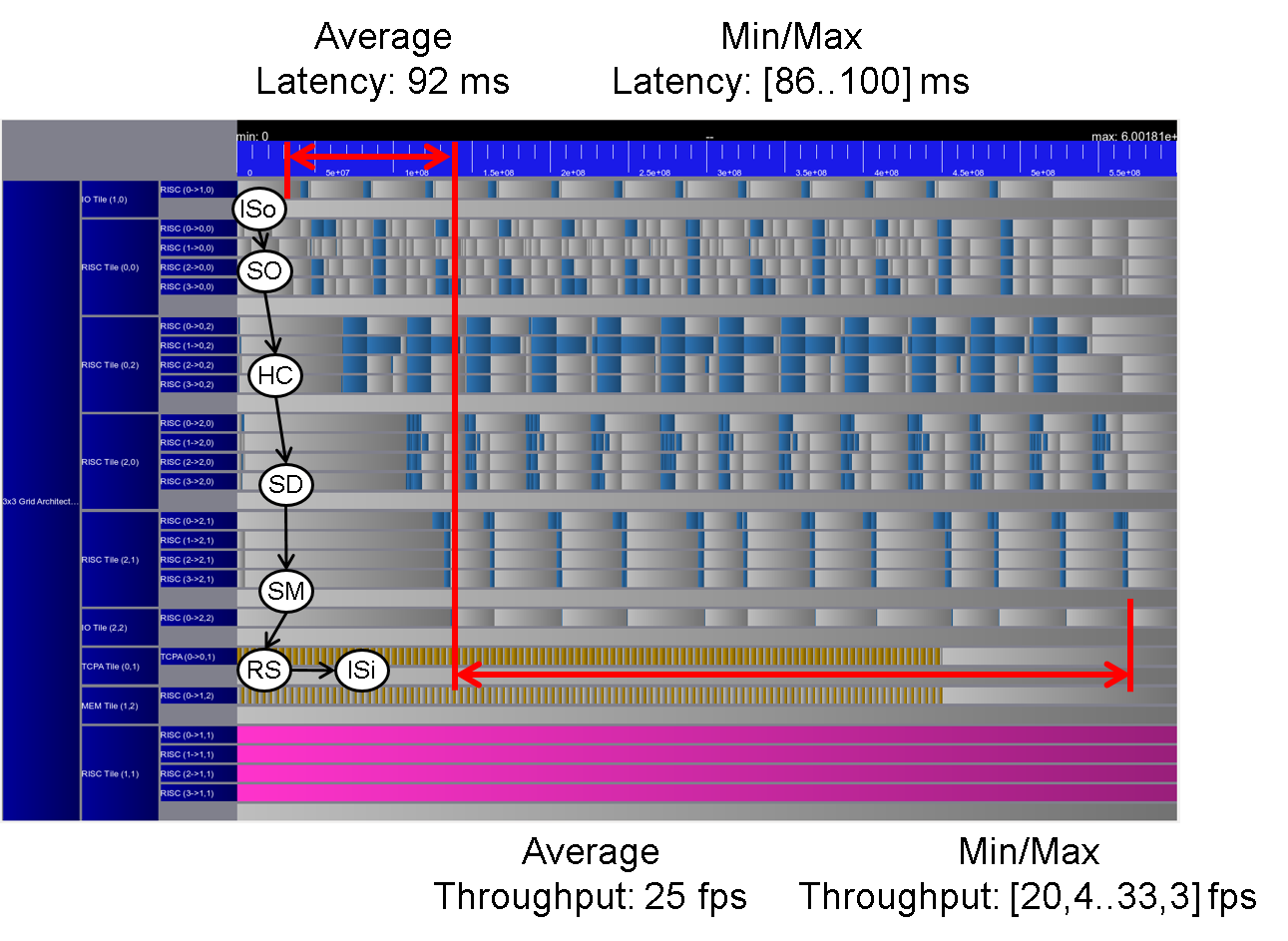
Figure 4: Trace scenario II.
Scenario III
In this scenario, the TCPA tile is not claimed by the object detection task chain.
Instead, a four quad core RISC tiles and two I/O tiles are used for it.
The resulting mapping of the different tasks to the tiles on the architecture is depicted in
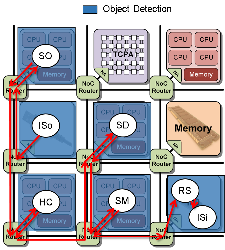
Figure 5: Mapping scenario III.
Video 3: Processor utilization scenario III (12 input images).
The simulation of this scenario results in an average latency of 86 ms and an average throughput of 25 fps as can be seen in
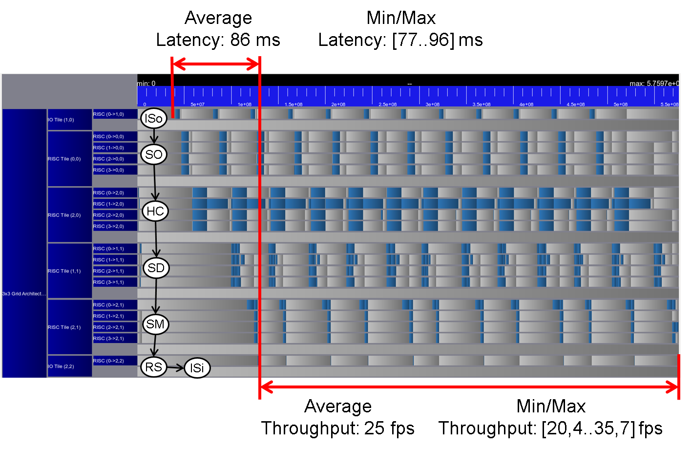
Figure 6: Trace scenario III.
Scenario IV
In this scenario, a TCPA tile is available and claimed by the object detection task chain for acceleration of the Harris Corner task.
The resulting mapping of the different tasks to the tiles on the architecture is depicted in
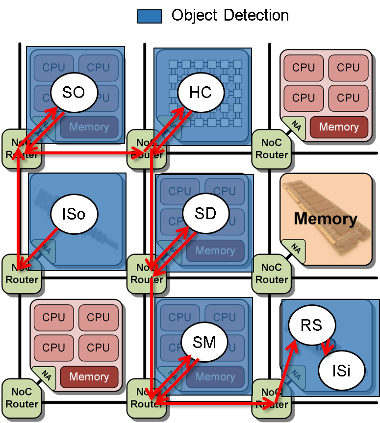
Figure 7: Mapping scenario IV.
Video 4: Processor utilization scenario IV (12 input images).
The simulation of this scenario results in an average latency of 57 ms and an average throughput of 52.6 fps as can be seen in
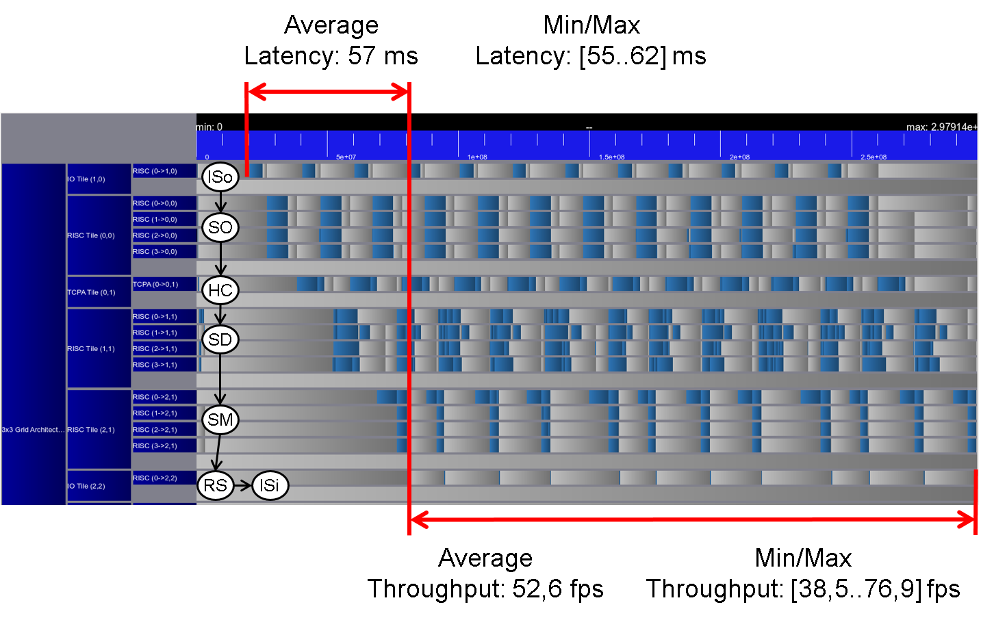
Figure 8: Trace scenario IV.